project overview
Building a Custom STM32/QMK Macropad
A close friend of mine, Ben, has served as a long-time sounding board and coding coach throughout my time making and breaking things. One of my current projects is a custom 3D-printed keyboard. Ben’s moving away soon, and I wanted to build him a custom board as a parting gift.
Being a developer, Ben already has a solid daily driver, so rather than leave him with some bespoke e-waste, we landed on building a slightly different device: a 5x5 load-out selector for Counter Strike 2.
I wanted to set myself a challenge to build this in a single weekend. To meet that deadline, I allowed myself to only use components I currently had in my possession. Ordering new things costs time and refusing to do that ensured I kept within my time limit.
Ingredients
If you’d like to create something similar, the materials I used in this project are as follows:
Core Components:
- 25 x Gateron Low Profile Red Switches
- 25 x Kalih Low Profile PCB Hotswap Sockets
- 25 x 1N4148 Signal Switching Diodes
- 1 x STM32F103C8T6 Microcontroller Board
Secondary Components:
- 22 & 26 Gauge Wire
- Elegoo Basic White PLA Filament
- BambuLab Matte Black PLA Filament
- M2 Screws & Threaded Inserts
- Self-Adhesive Rubber Feet
Tools & Equipment:
- A BambuLab P1S 3D Printer
- A Soldering Iron
- A Hot Glue Gun
- A USB to TTL UART Adapter
Software Packages
- Autodesk Fusion360
- Visual Studio Code
- QMK & QMK Toolbox, installed via Homebrew
- STMCubeProgrammer
Designing & Printing the Case
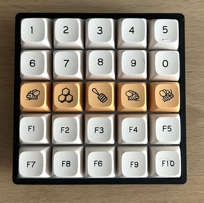
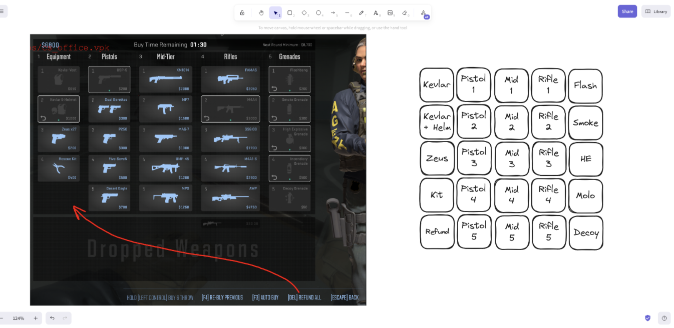
I’m not much of a CS2 player, so I asked Ben to sketch his ideal device. He shared a quick sketch of a 5x5 key grid mapped to the weapon select options shown in-game:
Taking this sketch, I created a mock-up of the device in Fusion 360 based on some modular components I’d developed previously for another board. The simplicity of the grid made this pretty straightforward:
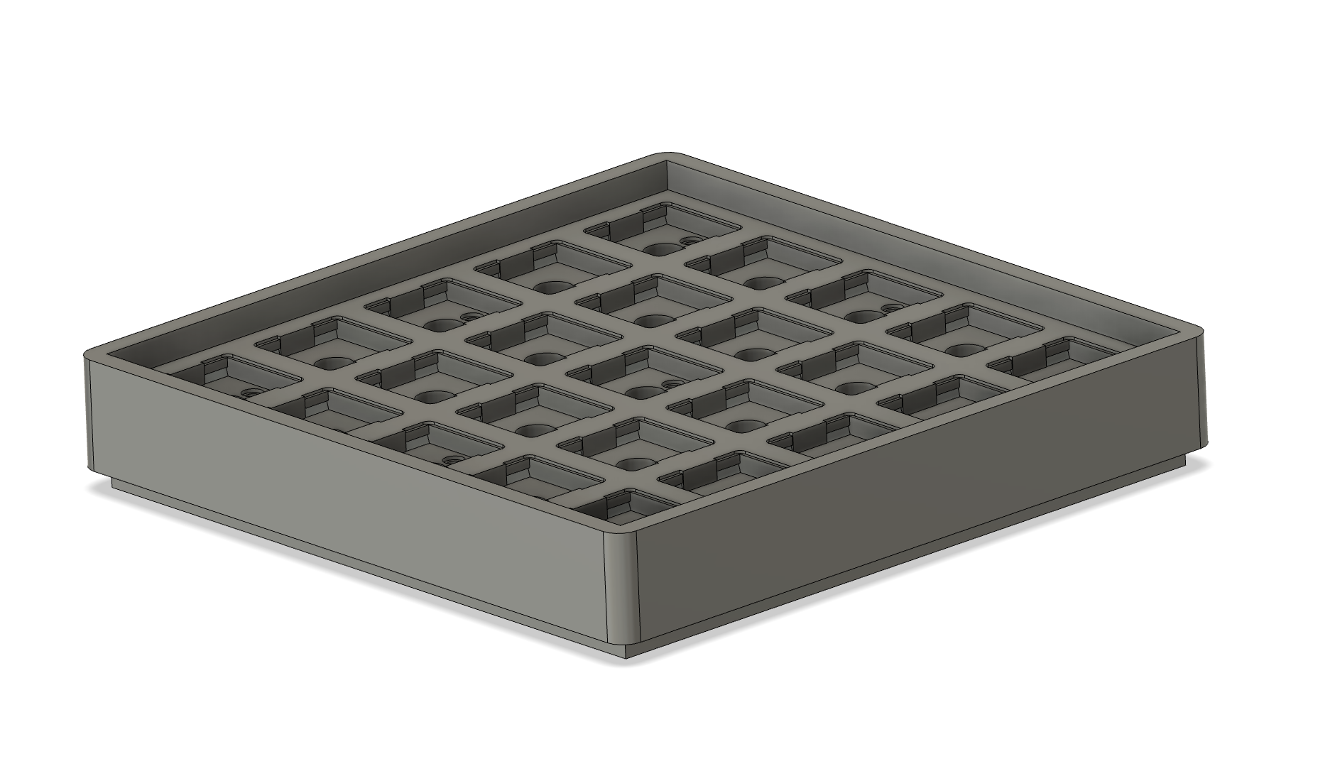
This model looked good, but I needed to figure out how to produce a functioning device with room for the controller board, switches and wiring. Iterating through the project, I landed on the following three-part case:
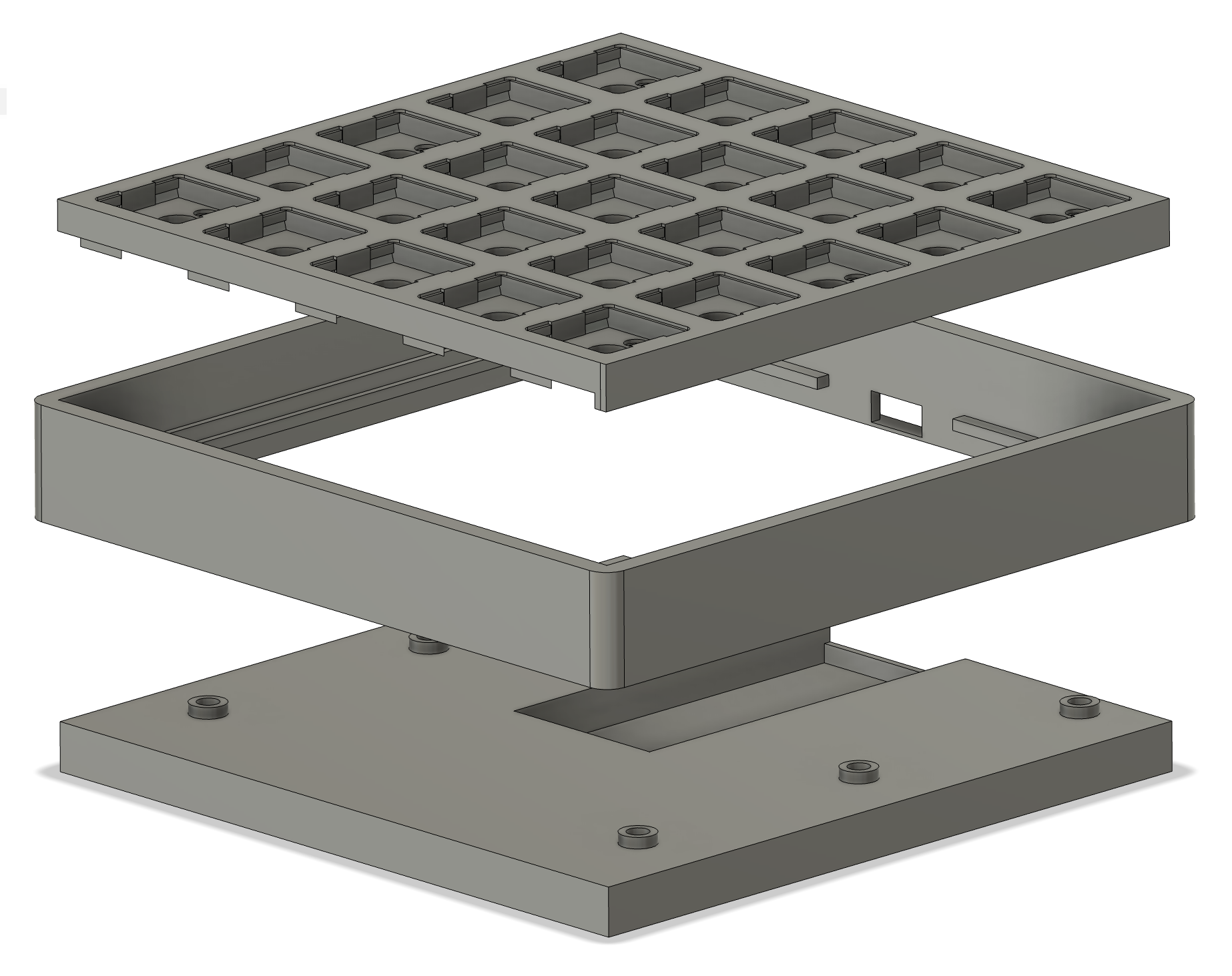
I made this case in three parts to give myself some margin for error and reduce potential wastage from iteration. It’s much faster to print a new rim or base alone than to print an entire bottom housing, and in turn it allows some wiggle room if fitting things together is a tight squeeze. Admittedly, this flexibility is at the expense of finish quality and ease of assembly, but as production volume wasn’t a consideration I could afford to make those sacrifices to expedite up the design process.
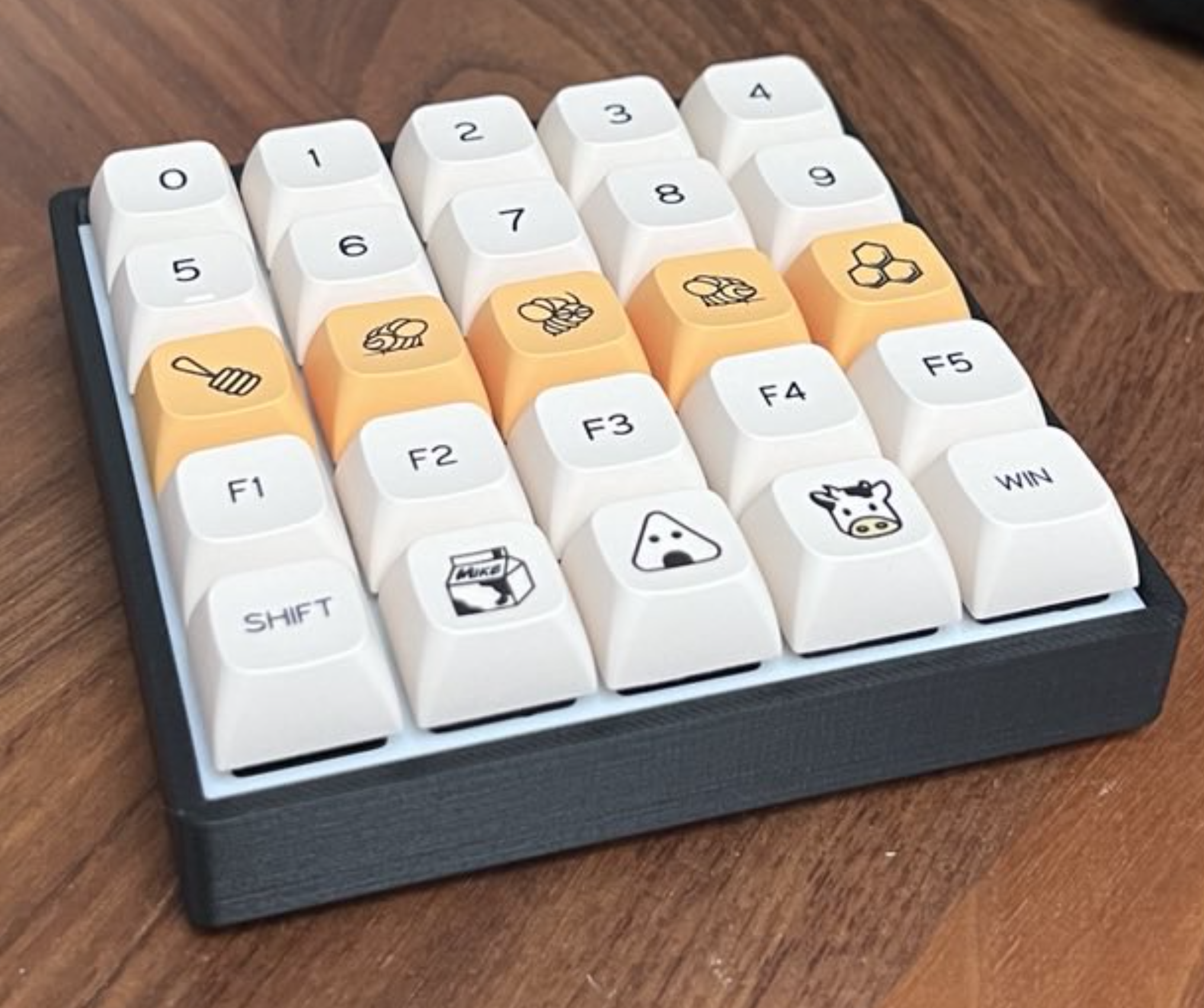
After printing I snapped in some switches and keycaps for a test fit to provide a sense of how the finished device will look and feel. I made some minor tweaks to improve overall tolerances and the spacing around the USB port before adding some finishing touches to the shell.
I used heated inserts in the baseplate to accept M2 screws which were hidden underneath the corner switches. This meant there were no visible connectors while ensuring future repairability should something go wrong. I opted to use the outside corners only to leave plenty of space for components, but if I were to produce a V2 I’d consider adding a centre screw, too.
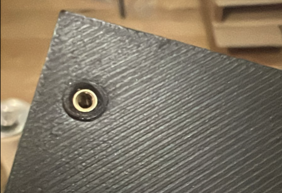
Admittedly this is not my finest work, but I doubt anyone is ever going to see this insert ever again.
Building the Matrix
Wiring up a keyboard matrix is pretty simple. Switches work in both directions (at least, the ones I had did - check yours first). One side of each switch is wired to its horizontal neighbours and the other to its vertical neighbours in a grid. This gives each switch a unique matrix position - the upper left key is at position (0, 0), the bottom right at (4, 4), etc.
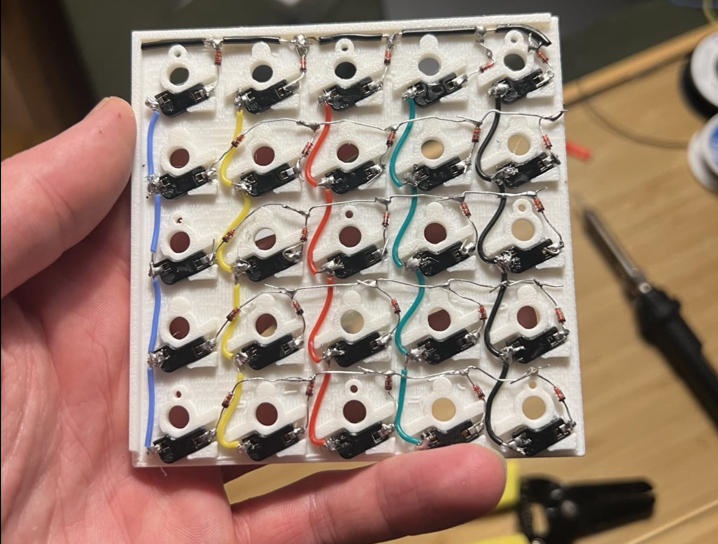
A thousand tiny burns later, I had a finished matrix. I used hot-swap sockets so Ben can upgrade the switches to match his preference should he wish to in future. These are designed to be PCB mounted, but I accommodated their dimensions into the plate design so they snap into place. This was a lot of work for only minimal gain, and I’d probably skip this next time.
I wired the diodes slightly differently from most hand-wired boards. Typically, you’d solder them oriented from Column to Row, but I oriented them from Row to Column. This is a personal preference and makes no practical difference provided they are in the right position relative to the switches.
You can also see that I gave up using insulated rows and instead used the diodes’ legs after the first row. This was a function of the available space and the fact I didn’t need to worry too much about insulation, meaning there was little benefit to the longer-winded approach. I’d strongly recommend putting in the extra effort for designs with any wire overlapping.
One error of judgment I made at this point was using CA glue to secure the sockets after wiring. I was concerned that the friction fit would fail over time with repeated use; I wanted to ensure longevity. While CA worked perfectly to secure the sockets in place, it also clogged a handful of the sockets and rendered them useless. I managed to salvage most of them with acetone and a steady hand, but I needed to go back and replace 5 sockets with fresh ones as I was afraid of dissolving the PLA and making a mess of the finish. If you’re following along, please learn from my mistake - use hot glue or print a back plate.
Setting up the controller
The hard part was over, but the keyboard still needs a brain. Thankfully, smarter people than me have spent years developing hardware interfaces, controller boards, firmware and software to solve this problem. Enter QMK.
QMK is an open-source firmware package for custom keyboards written in C. I’ve only used it a handful of times but have quickly become a huge proponent of the project. QMK supports myriad boards and microcontrollers that include ARM or AVR chips, and there’s a huge community and pool of resources available online.
I’d originally planned to use an ESP32 for this project, but unfortunately it’s not supported by QMK. Fortunately, I had some STM32 ARM-based “blue pill” boards to hand which are. These inexpensive boards can be purchased for less than £5 each and work perfectly, provided you’re willing to do a small amount of work to prepare them.
The specific microcontroller on the board I’m using is an STM32F103C8T6 with a single-core ARM processor clocked at 72 MHz. Many of these boards contain unreliable counterfeit chips from China, and some just flat out don’t work at all, but the parts I received from Amazon appear to use genuine components and function as expected. Make sure to read reviews and test thoroughly.
Preparing & flashing the board with firmware
The STM32F103C8T6 boards arrive blank and need a bootloader to function. A bootloader enables ports, manages I/O (including USB) and assigns a name to each pin that can be referenced in higher-level code (like QMK). It’s an analogue for the BIOS in a computer, but less standardised and stored directly on the microcontroller’s ROM.
Rather than trying to reinvent the wheel by writing my own bootloader to enable USB, I’m using the STM32duino binary built by rogerclarkmelbourne on GitHub.
I. Installing a bootloader over UART
The STM32 board I’m using has two jumpers on top; some boards have two push buttons, and others have unpopulated through holes. These jumpers tie two pins, BOOT0 and BOOT1, high or to ground. The voltage applied to these pins determines the boot configuration.
By default, both pins are tied low. When powered, the board attempts to boot from the onboard ROM, which is currently blank. By switching the lower jumper to tie BOOT1 high, the board will boot with UART communication enabled and allow flashing without an STMLink.
The board uses 3.3 volts, so ensure everything is at that logic level when using UART. The rest is simple:
- Connect ground to ground
- Connect 3v3 to 3v3 (or leave disconnected and power the STM via its USB port)
- Connect TX and RX from the TTL board to pins A9 and A10 on the STM board
Reset the STM board using its reset switch, and you should be able to connect via STMCubeProgrammer over UART. If successful, you’ll see the data currently on the device’s ROM - it should be all FFFFFFs or 000000s. If not, double check you have the RX/TX pins the right way around and that all of your connections are solid.
The steps from here are pretty self-explanatory. Locate the binary file in the browser, hit download, verify the write succeeded, and disconnect. If all worked according to plan, you should be able to switch the jumpers back to their default configuration, reboot the controller and see it recognised by your computer for the first time over USB.
II. Configuring, compiling and flashing QMK
QMK is super powerful and deserves a write-up of its own, but for the purposes of this guide, the steps needed to get to a functioning keyboard are simple once you figure them out. Unfortunately, there’s a lot of complex, often conflicting and outdated information online, so it can be challenging to wrap your head around exactly what to do.
I made use of two popular online tools to get set up. I started by mapping my layout using KLE and copying the JSON into KBF before configuring the matrix layout, key mapping and removing options related to RGB LEDs.
KBF is deprecated and I wouldn’t install the code directly from it to my board, but I find it really convenient for visually mapping out the locations of keys and their function in the browser. Once complete, I downloaded the firmware folder (not the compiled file) and headed to my terminal. If you’ve not worked with QMK before, now is the time to install it.
Using the QMK CLI, I imported and converted the legacy KBF files to a QMK configuration. This created a new folder in my QMK directory for the new board containing the JSON files that describe the configuration. The default settings KBF uses are for AVR boards, so I made the following changes to keyboard.json to match the hardware configuration I was using:
"bootloader": "stm32duino",
"diode_direction": "ROW2COL",
"debounce": 5,
"processor": "STM32F103",
"board": "STM32_F103_STM32DUINO"
This enabled me to build my firmware without errors using the CLI, which produced a single binary file to be flashed to the board. Flashing it is really simple with QMK Toolbox. I enabled auto flash, selected my new binary, and connected the STM32 board via USB. Within 10 seconds, the board rebooted, and a fully functioning HID was ready to go.
Finishing Up
With these steps complete and the case screwed together, the device now works as planned. If I had more time, I’d have tried to enable something like VIA, but I ran out of weekend before I could convert the JSON-based QMK to C, install VIA and rebuild. For now, Ben will have to rebuild and re-flash the firmware to change the keymap, but that process can be completed in about two minutes.
Overall, I’m happy with the end result. There are things I’d do differently next time - most notably, adjusting tolerances to give me more room to manoeuvre. Given the constraints I set myself, I consider it a great success.
The finished device feels sturdy, works well and feels great to use. I’m overall happy with the aesthetics, too. I used an assortment of old, scuffed caps for testing and photos, but Ben’s planning to change these out for custom caps soon. I’ll ask for a photo of the finished article when they arrive to share here.